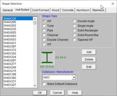
Shapes are organized by Shape Type and Database / Manufacturer. Common shapes are supported such as wide flanges, tubes, pipes, channels, etc. You may type in the names directly, select shapes from these databases or add your own shapes.
RISA currently supports the following common Hot Rolled steel databases: AISC (United States), Australian, British, Canadian, Chilean, Chinese, European, Indian, and Mexican.
Note:
To Select a Hot Rolled Database Shape
Note
For the AISC database, wide flange shapes are called out by the designation given them in the steel manuals. For example, if you wanted to use a W10x33 you would enter W10X33 as the shape name in the database shape field. M, S and HP shapes are also available. Trade Arbed shapes are called out similar to AISC shapes but with a “_ARB” suffix. I.e. to call a Trade Arbed W12X96 would enter W12X96_ARB as the shape name in the database shape field. Canadian and British shapes use the same format as the AISC shapes, but their values are metric. The depth is called out in millimeters and the mass per length is kg/meter.
The HSS tube properties are also available in the AISC database. The prefix for these tube shapes is "HSS". The syntax is "HSSdepthXwidthXthick", where "depth" is the tube depth, "width" is the tube width and "thick" is the tube thickness in number of 1/16ths. The nominal wall thickness is always used to call out a HSS tube, even though the design wall thickness will vary based on the manufacturing process for the tube. Tubes manufactured using the ERW process will use .93 times the nominal wall thickness as their design thickness. Tubes manufactured using the SAW process will use the full nominal thickness as their design thickness. For example, an HSS12X10X8 would be a 12" deep, 10" wide tube, and a have a design wall thickness of .465” = .93*1/2" (8/16ths) . A HSS32X24X10 would be 32” deep by 24” wide, and have a design wall thickness of 5/8”(10/16ths)
For the Canadian database, tubes also have a “HSS” prefix and the dimensions are all called out in millimeters. British shapes use the prefix “SHS” for square tubes and “RHS” for rectangular tubes.
Note:
Pipe shapes, which are hollow circular shapes, are entered as on-line shapes. The syntax for these shapes is "PIdiaXthick", where "dia" is the pipe outside diameter and "thick" is the pipe thickness (in inches or centimeters). For example (assuming US Standard units), PI10X.5 would be a 10" diameter pipe with a wall thickness of 1/2".
Channel shapes are entered with the "C" or “MC” prefix. For example C15X50 would be a valid entry. For Canadian and British shapes, the depth is called out in millimeters and the mass per length is in kg/meter. Double channels are entered with the “2C” or “2MC” prefix.
The Tee shapes are entered with the "WT", “MT” or “ST” prefix. For example WT15X74 would be a valid entry. For Canadian and British shapes, the depth is called out in millimeters and the mass per length is in kg/meters.
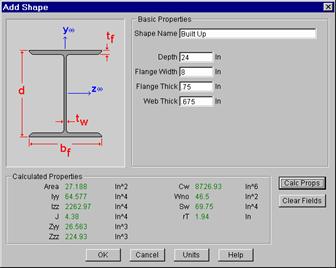
Tapered Wide Flange shapes are called out by referring to the shape name that was given when it was defined in the database shape editor. Tapered WF shapes can only be defined as database shapes using the “ADD” shape function in the database editor.
Tapered WF shapes are special in that the cross sectional properties change along the length of the member. This is as opposed to prismatic members, which have the same cross sectional properties along their length. (All other shapes are prismatic members). Keep this in mind when defining the I and J joints for tapered shapes. To obtain alternate tapered shape suggestions it is best to define all Tapered WF members consistently in the shape database and handle orientation with the I and J joints.
The Tapered WF shape can also be used to define a prismatic WF with unequal flanges. Tapered wide flange shapes can taper all cross section properties independently and can also have unequal top and bottom flanges. Each basic property is assumed to taper linearly from the Start value to the End value. Shape properties like the area and the moments of inertia will be computed at any required intermediate point from the linearly interpolated basic properties. (This means that the area and moments of inertia will probably NOT vary linearly along the member length). Intermediate shape properties are used to calculate the member stiffness and stresses. The member stiffness is computed internally from a series of piecewise prismatic sections. The error in the member stiffness computed in this manner, as opposed to the theoretically “correct” stiffness, is always less than 10%.
Note that tapered members are always treated as physical members – not finite members. All the rules and behaviors described for physical members always apply to tapered members even if the physical member flag is not set for those members. See Physical Members to learn more about this feature.
To Add a Tapered Wide Flange to the Database
Note
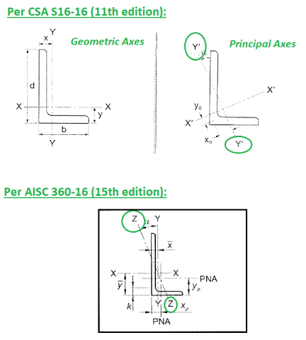
These shapes are entered with the prefix "LL". The syntax is "LLbackXflangeXthickXspace" where "back" is the back to back leg length, "flange" is the single angle flange leg length, "thick" is the angle thickness in number of 1/16ths and "space" is the space between the angles in 1/8ths. For example, LL6X3.5X5X3 would be L6X3.5 angles 5/16" thick, long legs back to back with a spacing of 3/8". For the Canadian and British shapes, all the dimensions are called out in millimeters.
Angles are entered with an "L" prefix. The syntax is "LlongXshortXthick", where "long" is the long leg length, "short" is the short leg length, and "thick" is the thickness, in number of 1/16ths. For example, L9X4X8 is a 9" by 4" angle 1/2" (8/16ths) thick. The thickness is entered as 8, because the number of 1/16ths in 1/2 is 8. For the Canadian and British shapes, all the dimensions are called out in millimeters.
Note:
These shapes can be defined as on-line shapes. The syntax is "REhtXbase", where "ht" is the rectangle height and "base" is the rectangle base (in inches or cm). For example, RE10X4 would be a 10" deep, 4" width rectangular shape (assuming US Standard units). These shapes can also be defined in the Shape Editor. When defined in the Shape Editor the depth of the solid rectangular section must always be greater than or equal to the width.
These shapes are defined as on-line shapes. The syntax is "BARdia", where "dia" is the circle diameter. For example (assuming metric units), BAR2 would be a circular bar with a diameter of 2 cm.
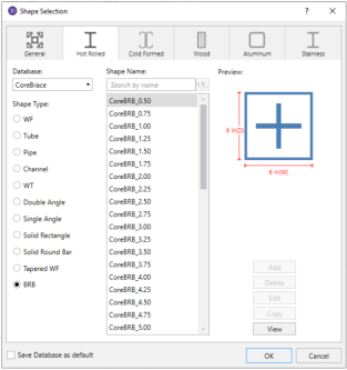
Buckling-restrained brace (BRB) shapes are only available in RISAFloor-RISA3D integration models. They can be selected by choosing the BRB shape type and one of the BRB-related databases. Currently, only CoreBrace database is supported.
When CoreBrace database is chosen, the syntax for CoreBrace BRB shapes is “CoreBRB_area”, where “CoreBRB” is the prefix for the manufacturer and shape, and “area” is the steel core area. For example, CoreBRB_0.50 refers to a BRB shape manufactured by CoreBrace with a 0.50 in2 steel core area. Other properties such as the casing size of the brace are based on the data provided by the manufacturers.
BRBs are not prefabricated with specific core sizes, casing sizes, or brace lengths. Instead, they are custom-fabricated for each project. Therefore the BRB properties in RISA-3D may not be the final and shall be carefully reviewed by BRB manufacturers.
Note: